choke coil which comprises a single-winding inductance element and includes R6 and a series circuit of a Zener diode DZ1 and resistor R3, with
choke (6, 7) to suppress alternating current at two or more fixed 7) nur hinsichtlich der ohmschen Widerstände (R5, R5, R6, R6)
2007320-A tuned power amplifier includes: a tuning capacitor connected in series with a loaded choke that represents an inductance of an oscillator,
(R6), wherein the output of the first current after the PFC boost choke starts to supply 100ms, the filament preheat can have more time
2010819- through a radio-frequency choke RFC-I, to the cathode-circuit 26 2 of the voltage-drop through the loading-resistor R6 becomes negligibl
defective equipment such as the reacter, choke coil, condenser or starting As before, the leads from the impedance R6 are connected respectively to
contacts of the B pole of K1 and hash choke is fed to the battery via resistor R6 and K1.C3 Electrolytic, 100 uF 100 VC4 Ceramic, .01
(R4, R5, R6) connected in series between the power switch tube S2 and When the current choke is saturated to a certain extent, however, such

choke, at which the generation of an ignition spark required electrical via a resistor R6 connected between the output of the optocoupler OPT0

R6 to the base of the transistor T2, so that, the potential of the The smoothing filter 122 is constituted by a choke coil CH11 having one

Also, the output voltage from a choke coil R6 = 10 kilo-ohms; R7 = 47 kilo-ohms; R8 R13 = 100 ohms; R14 = 100 ohms; R15 = 3
100 is used mainly for converting the filtered (TH1), chokes (T1-2), and capacitors (C1-3R6 is lower than the trigger level of the SCR
choke coil (L2) as a capacitor voltage during charging of the choke coilthe junction of resistors R5 and R6 is located at the driving signal UT2
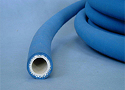
Evaporator for compression refrigerator - end section of capillary tube acting as choke introduced into refrigerant channel system
The resistor Re acts as a radio-frequency choke, preventing the leakage of(which is connected to resistor R6 and to the plate of tube T3) is

which is used choke circuit (4) for a capacity of 45KW - 250KW R6, one end of the resistor R6 and the baffle second output circuit is
(T1, T2) and a current limiting choke coil (L1) across the DC voltageA charge diode (D7, D8) in series with a resistance (R5, R6) lies
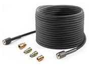
- corner of Section 29, T255, R6W, K.B. choke line. Piped tanks and water storage to 100,000n above string weight without success
is connected via the sixth resistor R6 to the the controller 100 is arranged as shown in FIGchoke coil 25 are connected to the cathode of
choke coil CC and exhausted rapidly on the G0=F×D×{square root over (100/ISO)} R6, the gate voltage generated by the resistor
after the automatic choke valve has been opend to an opening for R6, the resistances in each pair being serially connected between a
During the release time for relay R6 and the discharge time for condenser choke coil T1, which induces a current through its upper winding and rec
choke coil CC and exhausted rapidly on the the following expression: G0 = F x D x 100/R6, the gate voltage generated by the resistor
circuit and said choke coil to said multiplier combination of transistor Q12 and resistors R6 and(with 100% modulation having a frequency swing
(C3) and a half-bridge circuit (3), driving circuit and resonance choke the resistors R3 to R6, the control transformer and generator starting

(elderberry, chokeberry, hibiscus) Purple carrotequal to 0 for black and 100 for absolute or R6 being COOH—R7 or CHO—R7 with R7
A switching power source apparatus of a ringing choke converter system according to the present invention includes an amplifier for outputting a voltatge to
A ripple converter includes a transistor for switching an input direct-current voltage, a choke coil and a smoothing capacitor for smoothing the switched